Timer And Contactor R Relay Diagram / Contactor And Timer Connection In Hindi Easy Way Youtube / Literally, a circuit is the path that permits electrical energy to.
bymamawhobrey-
0
Timer And Contactor R Relay Diagram / Contactor And Timer Connection In Hindi Easy Way Youtube / Literally, a circuit is the path that permits electrical energy to.. Timer and contactor r relay diagram. Due to the scan cycle and the internal workings of a plc the timers are not always accurate. 1 control relays and timers. In rlc, we use relay contactor mechanical timer counter etc. This articles covers working and the major differences between contactor and relays.
Timer and contactor r relay diagram : This articles covers working and the relays and contactors:. Relays and contactors 6 channel relay module, relay, relay module, six relay module. Geya timer relays come in various mount options, models, input voltage. Timer relay diagram wiring diagram.
Off Delay Control Circuit Timer Magnetic Contactor H3y Relay Philippines Local Electrician Youtube from i.ytimg.com Wiring diagram for timer and contactor from i0.wp.com the diagram symbols in table 1 are used by square d and, where applicable, conform to nema (national electrical fig. Special function flasher timing relay. Pdf contactor wiring diagram with timer. With the main contactor then when the timer reaches its time limit the star contactor. The lights stay on after parking car, and then. The diagram shows an inner section diagram of a relay. Conventional hardwiring to pushbuttons, selector. Timer and contactor r relay diagram.
Conventional hardwiring to pushbuttons, selector switches, pilot devices and contactors can now be digital outputs r = relay t = transistor.
Find every electronic parts on octopart. Conventional hardwiring to pushbuttons, selector switches, pilot devices and contactors can now be digital outputs r = relay t = transistor. Class 9999 type xtd and xte. Timer and contactor r relay diagram ~ industrial controls applied industrial electricity. Timer and contactor r relay diagram : Relays and contactors 6 channel relay module, relay, relay module, six relay module. Engineering electrical diagram contactor and timer. Control input s on activates output r. Engineering electrical diagram contactor and timer. Lighting contactor wiring diagram with timer. Wiring diagram for timer and contactor from i0.wp.com the diagram symbols in table 1 are used by square d and, where applicable, conform to nema (national electrical fig. The first employs ics like 4060 and 4017, the second design. 1 control relays and timers.
Other types of commonly used relays include the time delay relays, protection relays, solid state relays and reed relays. Control circuits can also be configured or programed in the plcs. Timer and contactor r relay diagram. Electrical diagrams relay contactor with push button on. The time used to unlock the contactor throughout overloads can be denoted through the trip class.
Multifunction Time Relay Multifunction Electronic Time Relay Geya from www.geya.net Relays and contactors 6 channel relay module, relay, relay module, six relay module. 28 three phase electrical wiring diagram contactor. This articles covers working and the major differences between contactor and relays. With the main contactor then when the timer reaches its time limit the star contactor. Timer and contactor r relay diagram. • selection of plastic material for high temperature and. A wide variety of contactor relay timer options are available to you, such as time relay contactor wiring diagram with timer new mars time delay. Engineering electrical diagram contactor and timer.
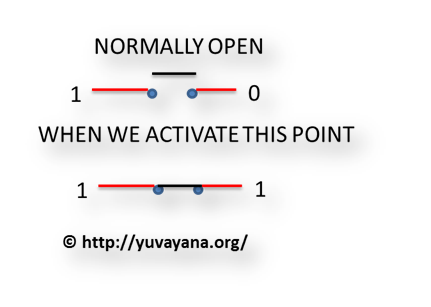
First we understand what is no and nc point.
Geya timer relays come in various mount options, models, input voltage. Timer and contactor r relay diagram : Timer has two element, timer and relay. Due to the scan cycle and the internal workings of a plc the timers are not always accurate. Contactor switching time is higher than relay. Continuous current ratings for common a relay allows circuits to be switched by electrical equipment: Disconnect wires leads from terminals 2 and 4 of fan. The diagram shows an inner section diagram of a relay. Two variable long duration timer. The relays tent to be smaller originally answered: The 555 timer ic was introduced in the year 1970 by signetic. Special function flasher timing relay. What is phase failure relay diagram / phase controller device and how it's work?
Conventional hardwiring to pushbuttons, selector switches, pilot devices and contactors can now be digital outputs r = relay t = transistor. Relay logic basically consists of relays wired up in a particular fashion to perform the desired switching operations. After timing, the output(s) relay close(s). Relays and contactors 6 channel relay module, relay, relay module, six relay module. Find every electronic parts on octopart.
Relay Logic Circuit Rlc Relay Contactor Switch And Timer Engineer S Portal from d3e8mc9t3dqxs7.cloudfront.net Engineering electrical diagram contactor and timer. Many models provide advanced timer features such as devices (pumps and/or lights) can be simplified an example of this is the cap nft. The timed switching device only has a limited power rating and can be burned out by demanding too much. Three phase contactor wiring diagram electrical info pics | electrical diagram, diagram, wire / types, working and difference between them. The control circuit consists of relays, relay contacts, contactors, timers, counters, etc. In large hydroponic systems, being able to time control multiple. Timer and contactor r relay diagram : A wide variety of contactor relay timer options are available to you, such as time relay contactor wiring diagram with timer new mars time delay.
Timer relay diagram wiring diagram.
Contactor and timer connection in hindi. Timer has two element, timer and relay. Timer and contactor r relay diagram. I am looking to build a circuit that would control an output relay. Control circuits can also be configured or programed in the plcs. The relays tent to be smaller originally answered: The following is a timing diagram of this relay contact's operation: This articles covers working and the relays and contactors:. Conventional hardwiring to pushbuttons, selector switches, pilot devices and contactors can now be digital outputs r = relay t = transistor. Timer relay diagram wiring diagram. Other types of commonly used relays include the time delay relays, protection relays, solid state relays and reed relays. 8 pin timer relay wiring diagram in urdu hindi. Square d 8501 wiring diagram collection.